The magic of OFDM
I’ve been playing a bit with OFDM in software defined radio lately. And after watching a video that wasn’t even close to correct, I thought I’d write down my understanding in a blog post. I wouldn’t call myself an expert, so worst case someone will correct me, and I’m happy to be corrected.
In my experiments with OFDM my initial goal is understanding, so e.g. I won’t blindly use some hierarchical GNU Radio block.
I/Q and the actual analog signal
I think that in order to internalize OFDM, we first need to remind ourselves how a purely “real” wave becomes a complex number, at a high level.
The real signal is a value that’s a function of time. Glossing over details, this is not feasible for most of our signals, as we would need to provide a new value to the transmitter at a rate twice as high as the highest frequency we care about. For 2.4GHz experiments, we’d need 4.8 billion samples per second.
Quadrature sampling allows us to represent a slice of bandwidth at a manageable rate. We can then provide the I/Q data to hardware, instructing it to hold that “until further notice”. If we provide one sample per second, for example, we can change the phase or amplitude of a pure sine wave (the carrier) once a second. Between our samples, it continues as-is in that phase and amplitude.
“As-is” is here left deliberately vague. I only phrase it this way because it’s a helpful analogy further down.
QPSK
Now some background on QPSK, since that’s the encoding in the subcarriers in my OFDM experiments. This should apply equally to QAM, QAM being a generalization that allows more bits per symbol.
At first glance QPSK seems simple. Symbols become +-sqrt(2)/2 +- j*sqrt(2)/2.
But you can’t really transmit that kind of instant transition without infinite
bandwidth. An individual symbol instead gets turned into a “pulse” towards its
coordinate. A pulse will spread out, but the pulse shape is designed such that
it should have minimal effect where it matters; at the peak of neighboring
pulses (symbols).
So if the receiver samples at exactly the right point, it’ll get a perfect symbol with no inter-symbol interference. Of course that’s only strictly true in theory (because of multipath and various nonlinearities). But minimizing the symbol interference helps.
Turning symbols into pulses is called pulse shaping.
GNU Radio has a nice guide to QPSK.
OFDM
The explanation of OFDM still makes me feel like it shouldn’t work. It’s too weird of a tool to use. It feels like cheating.
The idea is that instead of having one high symbol rate with as many constellation points (and therefore bits per symbol) as you can, you instead split your data into multiple slower carriers of narrower bandwidth.
How would you generate all these smaller slower signals? Well, you could create many virtual transmitters and add them up into one spectrum. That’s one way to turn many constellation diagrams (series of complex numbers) into one signal. Then on the receiver side you’d do one band pass filter and translation to baseband per carrier.
You know what else takes a complex time domain signal and gives you a set of discrete complex numbers, one per frequency? An FFT.
So you just stuff QPSK symbols into (e.g.) 64 FFT bins, and do an inverse FFT? Well, almost (see below). But the fact that the answer is “yes almost!” is what’s magic. This is the thing that blew my mind.
A receiver can then just do a 64 bin FFT, and there you have the I and Q for your 64 subcarriers.
This means that both transmitter and receiver will process the incoming I/Q in chunks. Chunks that are the size of the FFT.
As a tangent, FFTs can do other magic things too, like this amazing talk on whole packet clock recovery.
What is an OFDM symbol?
Ok, so “OFDM symbol” doesn’t make so much sense. I mean the collection of symbols being sent at any given point in time across all subcarriers.
An OFDM “aggregate symbol” is several input symbols, distributed into the FFT bins / subcarriers.
Transmitting turns these sets of symbols into
for ofdm_symbol in symbols_to_transmit.chunks_exact(64) {
    for sample in inverse_fft(ofdm_symbol) {
        enqueue_transmit(sample);
    }
}
I found it useful to think of OFDM in the time domain within a single “FFT chunk”. The original I/Q samples had a start time and an end time. Between the start time and the end time, the true analog signal was a mix of (for example) 64 fixed tones. The individual tones had a particular individual phase and amplitude.
Here’s an example of a four-subcarrier OFDM, for three symbol periods:
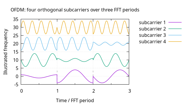
And this is where the “hold this until further notice” analogy is relevant. For a given subcarrier, the frequency is (by definition) fixed. It doesn’t matter how many cycles a given subcarrier goes through. It just matters for a given subcarrier, what amplitude and phase it was. Subcarrier 1 has one, subcarrier 4 potentially has another.
And yes, this is the same thing as having four independent transmitters. But because the “transmitters” are just the output of an inverse FFT, they are exactly synchronized. We generated these four transmitters by cheating!
What about pulse shaping?
Taking the illustration above literally, we should not transmit that exactly. The phase and amplitude transitions are too sharp.
An input symbol is only part of one FFT, and for the next FFT period we have another input symbol for that FFT bin.
So how should we soften that up? Should we pulse shape the subcarrier QPSK before it goes into the inverse FFT? No, because then that means each symbol takes multiple FFT chunks, slowing down the transmission.
Do we pulse shape the whole FFT chunk? Yes, kind of. Fixing this involves windowed OFDM/WOLA, smoothing out the FFT period transitions, and I’ve not looked into it yet. Currently my testing just uses rectangular window FFTs.
Multipath
OFDM is good in the presence of multipath for two reasons:
- The symbols are slow, and the speed of light is fast. The slower a symbol is sent, the less the chance a bounced signal from a different symbol has to interfere.
- OFDM also encourages adding a “Cyclic Prefix”. Basically extending the transmitted “OFDM chunk” and discarding the initial part, under the assumption that it could be polluted with multipath echoes of the previous symbols.
The Cyclic Prefix adds another benefit for receivers I’ve not yet internalized.
Frequency locking
Whereas QPSK needs to lock on based on peaks in the signal followed by carrier recovery, and can therefore easily lock in on small frequency differences between transmitter and receiver, OFDM doesn’t have the same luxury.
The pulses are inside the subcarriers, and you can’t extract the subcarriers until you have the frequency.
This is usually solved by sacrificing some subcarriers to pilot signals. In my testing I made the center bin a pure sine wave, and used a feedback loop to perform a primitive frequency lock based on quadrature demod.
Using the center bin for Pilot has a potential benefit that some SDRs will sometimes fail to be quiet there, because that’s their location of the local oscillator.
Any residual frequency error will result in cross-subcarrier interference, and frequency offset (quadrature rotation) inside the subcarrier.
You can also use a Jacobsen CFO estimator to estimate the frequency error from the pilot signal FFT bin. My GNU Radio flowgraph uses that only for diagnostic, not for tuning feedback.
On the plus side, because the subcarrier is merely the values of the FFT, if the outer carrier is synchronized, then the inner is too, and you can just pluck the QPSK symbols directly after Symbol Sync, without a Costas loop or other subcarrier frequency lock. Well, it’ll likely need to correct for minor phase errors. In any case the Costas loop sure has an easier job, that it can do with a smaller bandwidth.
In my example graph, the default frequency locking is coarse, trading stability for speed of convergence, and the clocked symbols (under “Clocked”) shows this instability as a subcarrier frequency offset, correctable with a Costas loop.

If I change the coarse_lock_alpha to a lower value, it becomes stable:
 (yes, that’s an animation. It’s just very frequency locked)
In a better implementation, frequency locking should probably switch to fine locking automatically when the signal is found.
Timing synchronization
While my GNU Radio experiment does add the Cyclic Prefix, and removes it, it does not yet actually attempt any timing synchronization. This means that the start and end of an “FFT chunk” can be wrong. I think this is a likely main cause of why it’s very sensitive to other subcarriers being assigned random phase noise:

I think this timing synchronization may be best done by having the pilot signal do… something. Maybe the (or one of) the pilot signal should be BPSK triggered by FFT chunk transition?
My helping LLM calls that a “poor substitute for a synchronization preamble or CP correlation”, so then again maybe not.
OFDM on the spectrum
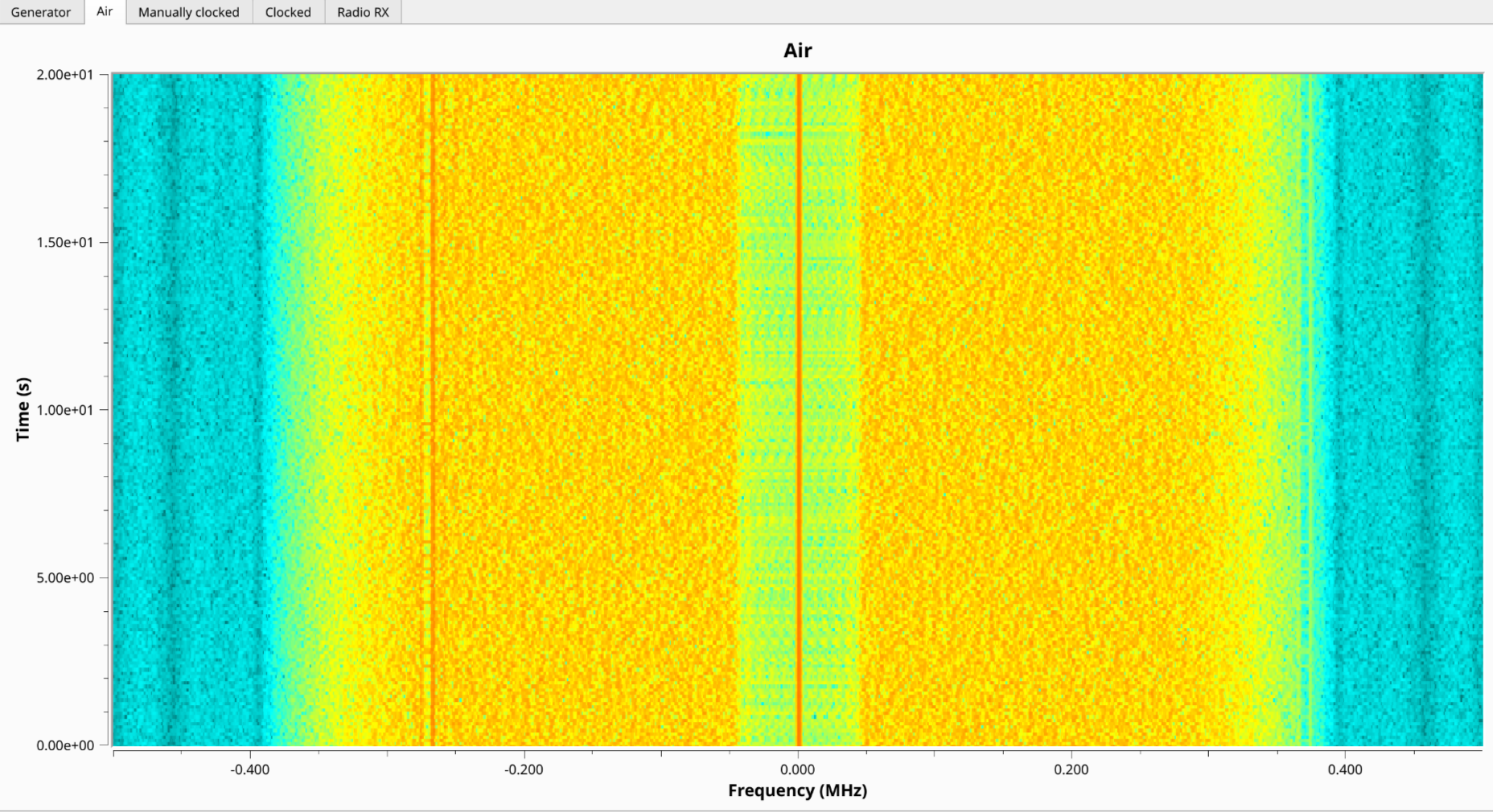
This is how my OFDM test looks over the (virtual) air. A pilot in the middle, silent bins around it, a slow (each symbol repeats 10 times) signal in FFT bin / subcarrier 5, and the rest of the carriers full of noise.
My test flowgraph
This blog post was written when the github repo with my flowgraph was at commit 1e8fbd79d465cf94f6407f4677375ac088158619.